Tag Archives: motor

Open-BLDC and the CLogic story

Castle ICE HV to Open-BLDC Mod Tutorial Step 10

Hi,

It was again a while since my last post, but as always I was quite busy. 🙂

The last news about Open-BLDC was about its V0.3 iteration. A lot has changed and happened since then. I was realizing that I am getting more and more inquires where people were asking about obldc being able to control very different sizes of motors, ranging from 12V and 10A up to 48V and 200A.

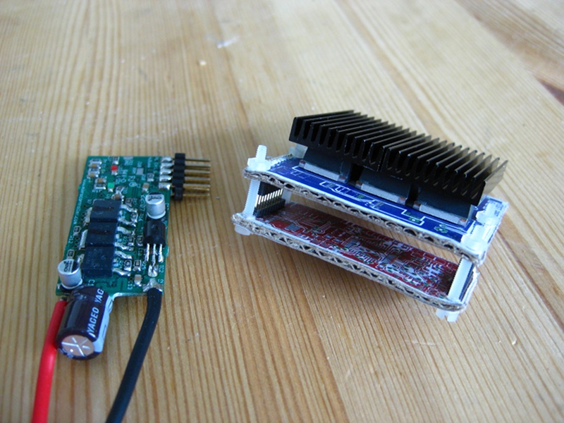
This requirement does not really ask for different logic and controls but it definitely asks for many different power stages. Open-BLDC was designed to be modular from the beginning but still to accomodate that kind of a power range it would be necessary to design and create quite a big lineup of hardware.

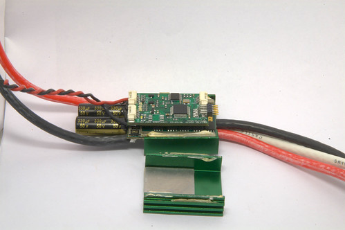
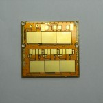
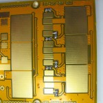
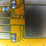
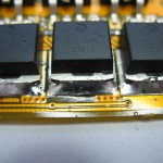
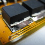
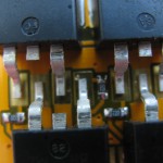
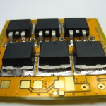
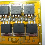
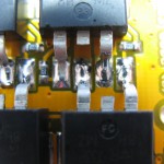
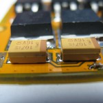
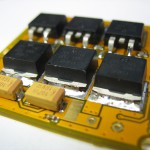
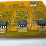
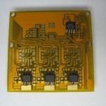
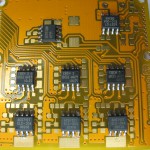
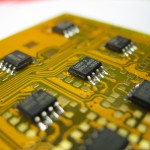
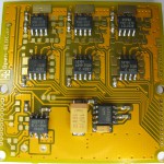
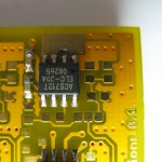
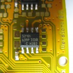
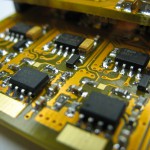
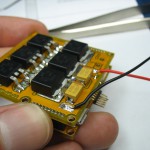
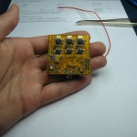
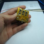
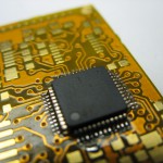
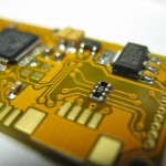
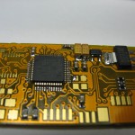
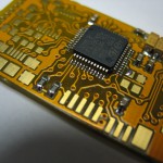
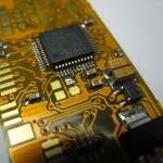
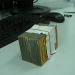
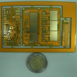
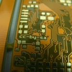
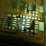
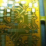
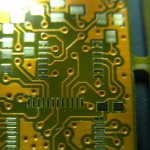
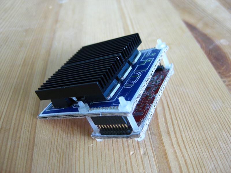
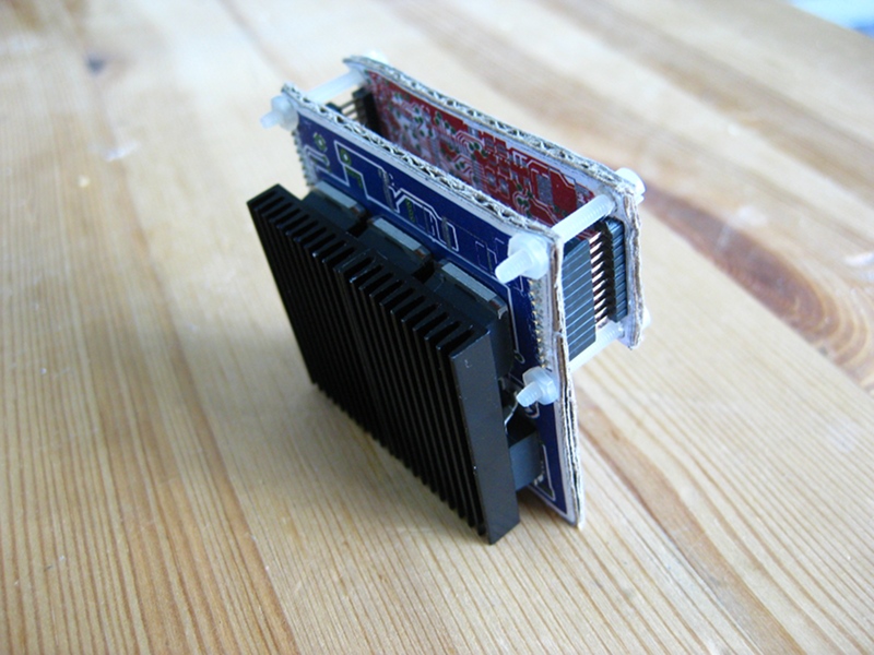
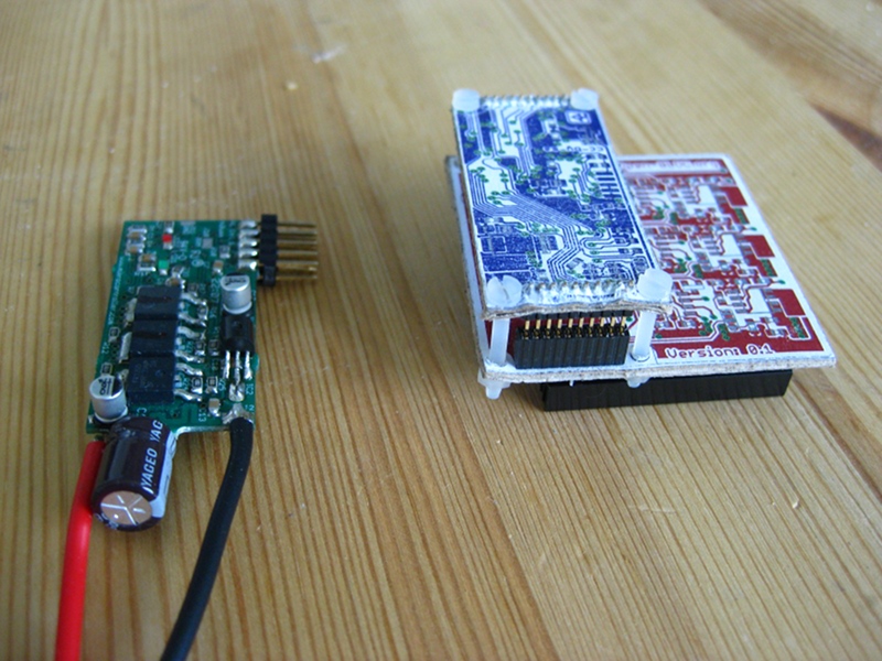
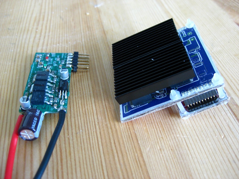
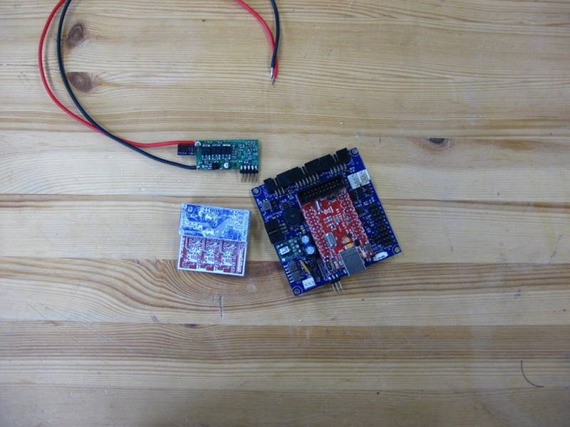
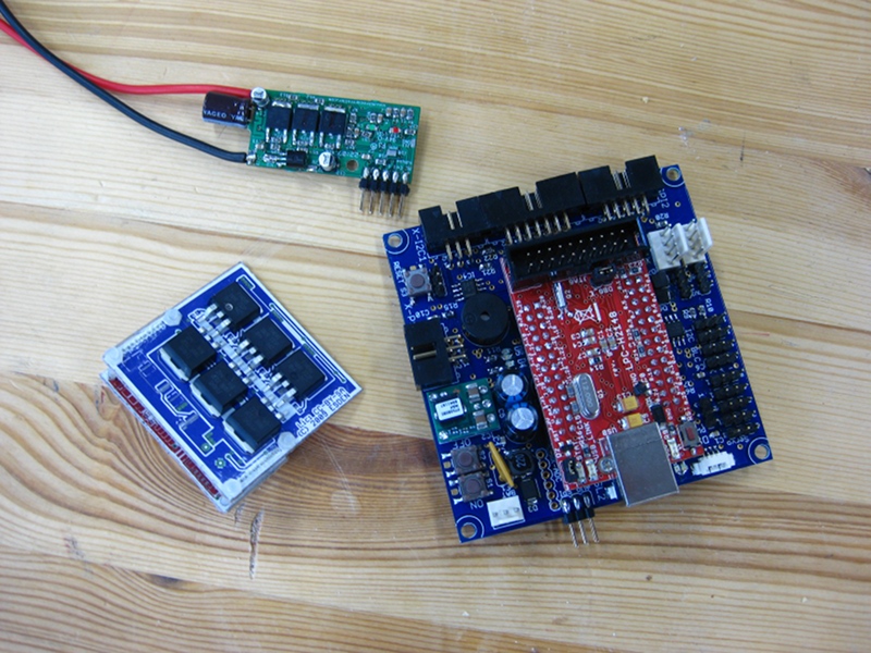
Around that time I had the opportunity to take a look inside a dead motor controller from Castle Creations just to realize that these guys seem to know what they are doing and that they went with a modular design too. To make a long story short I decided that it will be better to buy one of their of the shelf motor controllers and retrofit them with my logic. That is how CLogic was born.

As it seems other manufacturers are selling ESCs that have the same interface between the logic and the power stage too. Tekin for example. But my guess is that they are just OEM of castle themselves. But who knows. 🙂

Turingy also came out with an ESC that seems to have the same interface, the Turingy dlux. I ordered a few of them to take a look for myself and see if CLogic will fit in there. That would be a great source of cheep power stages. 🙂

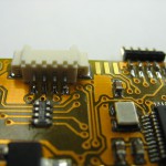
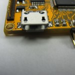
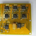
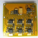
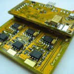
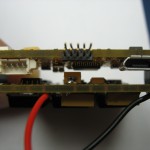
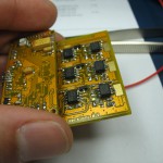
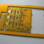
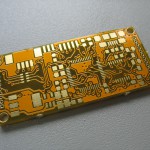
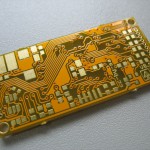
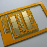
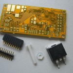
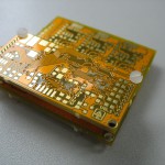
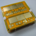
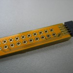
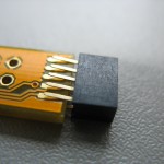
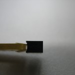
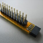
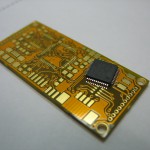
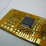
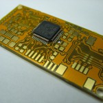
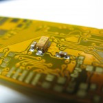
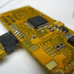
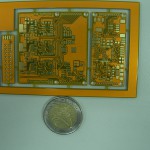
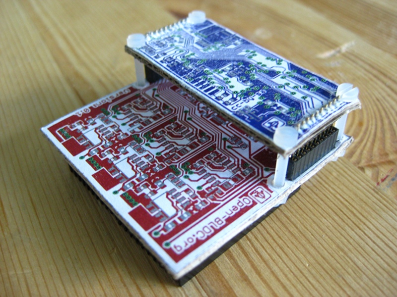
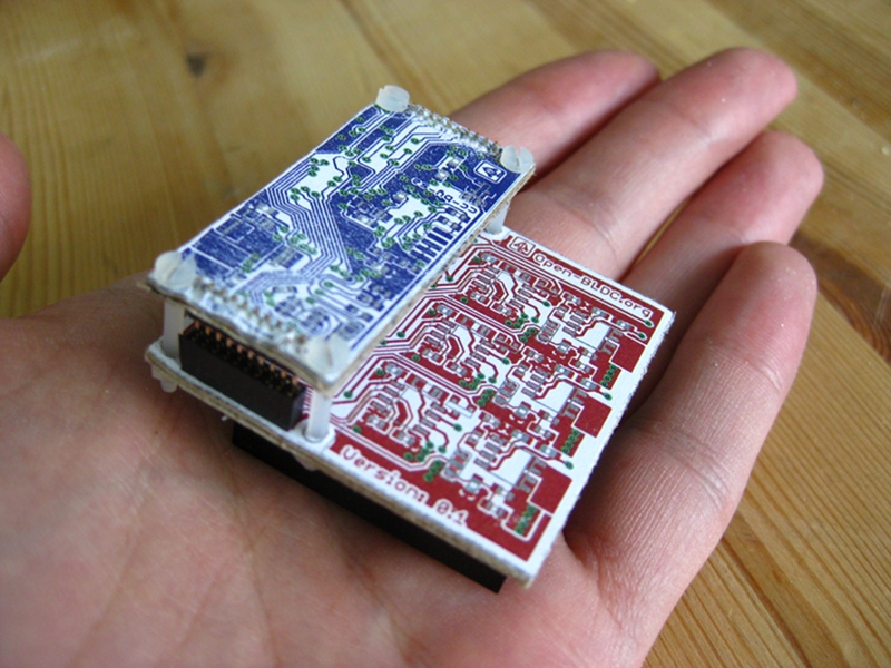
CLogic has most of the functionality the Open-BLDC v0.3 had. Because of the size constrains I had to get rid of the dedicated i2c and PPM connectors, but I added isolation on the CAN interface that should provide additional safety when used on a 50V and bigger systems. The i2c and PPM interfaces are still available either over the new AUX connector or through the UART interface connector.

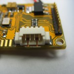
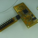
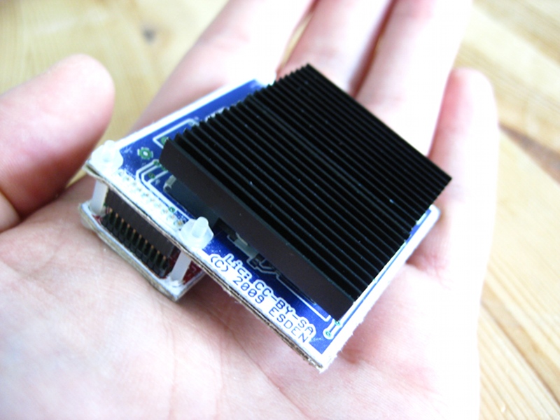
The new AUX connector gives the possibility of easily connecting encoders or hal sensors for sensored operation. So the interfaces stay very flexible with added flexibility due to the big variety of power stages you can use, while being very very compact.

Sure some people complained “The power stages are not Open-Source!!!”, yes that is true. Also these systems start at a higher power and weight class than some of you would want to operate them. That is why there is CPico Power. It is a very small, low power and a hopefully cheep power stage that we are putting together for those who want it all fully open! So no worries. 🙂

I think that wraps up the news about the new direction Open-BLDC is going. I hope you like it. I am looking forward to your comments.
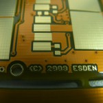
Cheers Esden

Open-BLDC V0.3 Hardware Based Closed Loop Control

Hi,

Good news everyone!

After again a way too long time some new news! I finally implemented hardware based commutation detection and the associated closed loop controller.

That was quite a run because of a cascade of timing and timer problems. And a very nasty compiler bug. But now it works and very well on top of that. Woohoo o/ But see for yourself in the video.

The video also shows the new implementation of the startup routine. It uses now a separate software timer. It was made possible by using SysTick as timer base and implementing the timer in software. This way it is easy to add new timers that don’t need to be very time precise, as it is the case in startup, or ignite as I like to call it. 🙂 The old implementation was using timer overflows of the commutation timer that led to nasty speed jumps while starting up and made the startup unreliable.

Next step, put Open-BLDC on a plane! 🙂

As always you are welcome to drop by in #open-bldc channel on freenode if you have questions or just want to hang around to follow the cutting edge development. 🙂

Open-BLDC Documentation

Today was a big documentation day for Open-BLDC.

As Tobi is learning about Open-BLDC to be able to help me with development I really felt the lack of documentation. So together with him we wrote down how the ignition system currently works. Also I added a getting started page describing how to build the firmware.

Last but not least (that took me most of yesterday) I finally managed to add doxygen generation to the firmware code. It is even being automatically generated out of the git repository and making it available on http://doc.open-bldc.org.

There is still a lot that can be told about the system, but I think we are on the right path. The documentation should grow now significantly when I am not the only person working on the code. 🙂

Open-BLDC v0.3

Open-BLDC V0.3 Full Front
Hey everyone!

Just a short update so that you don’t think that I have disappeared completely. 🙂

Lately I am really busy so that is why my updates here are very rare. I have moved to California few months ago to work full time on Open-BLDC and Paparazzi. Although Open-BLDC got quite a bunch of attention there is still a lot to do, and this project is still not in a state where it is possible to put the controller on a vehicle and fly with it. 🙁

There is some good and bad news. I got the sampling based commutation detection running pretty good. There is an issue with it. Because you can sample the BEMF only once a PWM cycle the resolution prevents turning the motor very fast without adding some kind of an estimator or at least a PLL. So currently only 4000RPM with a 7pole pare motor are possible. 🙁

That is why I started working on Open-BLDC v0.3 hardware. It is assembled now and you can look at some pictures here. It has a comparator integrated into the power driver board to make commutation detection really easy and have something usable _NOW_. I also found out that using many small mosfet’s is much more efficient then using single big ones. The gate capacitance is lower, the heat dissipation is easier, the on resistance is tiny. The only question is if they will distribute the power evenly between the switches. That is still something that has to be tested. But the power stage board looks really pretty with all those tiny fets on it. There are many more other smaller and bigger improvements that would be too much for such a small post.

I am currently bringing up one subsystem after another. I had to change some of the connections to the STM32 which means that I have to change the low level drivers and it is always a pain to do.

Anyways, there is progress and Open-BLDC is not dead! I am working on it. And I am sorry for not keeping you guys more up to date. As always I will try to be better about that. 😉

Open-BLDC V0.1 Fully Assembled

I finished soldering Open-BLDC V0.1 boards and took some pictures while doing so.

After connecting it to the power everything seems to work properly and nothing is burning. That is really good news.

One little thing that is bothering me. The board draws 60mA, what is a value that I expected. The 5V linear regulator gets really warm. I am not sure if that will be a problem or not. But I did not find any other problems or screwups yet, even the big MOSFETs can be soldered using a simple soldering iron. It takes some time though, because the board and the MOSFETs are monstrous heatsinks.

More news coming up as soon as I start playing around with the software.

Open-BLDC V0.1 is alive!

I assembled the basic STM32 circuitry of Open-BLDC and it works. I also made a video showing the logic board and blinking around. I know it is a bit pointless but I love blinking LED’s! 😉 I wrote the software using libopenstm32.

Have fun:

Video on Youtube and here the same video on Vimeo.

While assembling Uwe and I made some photographs that I don’t want to hold off either.

Open-BLDC V0.1 boards are here

Good news everyone! The Open-BLDC boards are on my table. If you ask me they look gorgeous. 🙂 But decide for yourself …

Cheers Esden

PWM Schemes/Fieldvector Control

Some time ago I announced the Open-BLDC project in the Mikrokopter Forum, the post, that you can find here inspired a very interesting Discussion. One of the topics were PWM Schemes and why one should think about them. The most important reason is efficiency. Most controllers to use H_PWM_L_ON or H_ON_L_PWM schemes. An alternative is PWM_ON_PWM scheme which prevents currents through freewheeling diodes connected in parallel to the MOSFET’s. The freewheeling diodes have higher losses then a MOSFET. I am really asking myself why it is not used. One reason I can think of is that this scheme has 12 steps instead of 6 and therefore is more difficult to implement and BEMF measurement for commutation detection may be more complicated.

Another approach to the efficiency question may be using fieldvector control. This involves a sinusoidal pwm scheme and current measurement on the phases. Using that way of control should decrease torque ripples which are typical the other schemes mentioned above. It also involves a lot more work on the firmware side.

I started building a rig for testing the efficiency of the different schemes. It involves a harddisk platter connected to the motor and two harddisk magnets. At the end I will have a eddy current break and can measure how much current is needed to achieve a specific rotation speed. I hope that this way I will be able to make a more or less scientific comparison of control approaches.

If you have a motor controller I would be really happy if you could take an oscilloscope and record the voltages on the phases. I am really interested what control schemes others use.

Open-BLDC mockup

Hi!

As you already know I have layouted the Open-BLDC boards. I was not sure if everything fits mechanically. So I took some cardboard and created a mechanical mockup. It really looks good! It is darn stable (even though it is only cardboard and not FR4) and the screws fit snugly. I think we are getting really near to a state where I can order some boards.

You can take a look at some images attached to this post.

Have fun! 🙂

Open-BLDC SMD prototype and final prototypes

Open-BLDC SMD Prototype

Open-BLDC SMD Prototype

It has been again a long time since the last post. (I have the feeling to repeat myself here)

There have been some news on the Open-BLDC front. I have been on Motodrone two weeks ago. Because I took the plane to get there I realized that it will be too difficult to take the breadboard prototype with me. So on a short notice I soldered together a smaller version using smd parts. As an extra feature this prototype includes Allegro hall based current sensors. These will enable us to investigate vector control (aka. field-oriented control).

At first it worked perfectly. Sadly after some tests I burned two of the three bridge drivers. I only had one spare to replace, so I could not work on the software for long. Today I got replacement bridge drivers. Now I should have enough spare ones to compensate for more burning. 😉 So no news on the vector control front yet.

Open-BLDC Logic Board V0.1

Open-BLDC Logic Board V0.1

Open-BLDC Powerstage V0.1

Open-BLDC Powerstage V0.1

But I was not lazy while waiting for the replacement parts. I finalized the circuit and routed the logic board and powerstage. The powerstage was more or less straight forward but I am not very happy about the size and dimensions. I just am not sure if it is fittable on a standard Quadrocopter. Still it should be good enough as first etched prototype.

A much bigger challenge was the logic board. I somehow came up with this crazy idea to constrain the size of it to 45mm X 20mm. Still after many many hours of struggling with that puzzle I managed to squeeze all parts and wires into 45.5mm X 21mm! Yes you are right I am pretty proud of myself. I am still a routing beginner so the result seems to be good for me. 🙂

Now I have to wait so some other people review the work I did to try decreasing the amout of possible bugs in this boards. (If you like you can clone the repository here and check the stuff out, and give feedback on the mailinglist. (please subscribe before posting! :/ )) When I feel confident enough I will order some boards for testing and we can finally concentrate more on the software. 🙂