Hi,
It was again a while since my last post, but as always I was quite busy. 🙂
The last news about Open-BLDC was about its V0.3 iteration. A lot has changed and happened since then. I was realizing that I am getting more and more inquires where people were asking about obldc being able to control very different sizes of motors, ranging from 12V and 10A up to 48V and 200A.
This requirement does not really ask for different logic and controls but it definitely asks for many different power stages. Open-BLDC was designed to be modular from the beginning but still to accomodate that kind of a power range it would be necessary to design and create quite a big lineup of hardware.
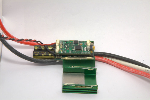
Around that time I had the opportunity to take a look inside a dead motor controller from Castle Creations just to realize that these guys seem to know what they are doing and that they went with a modular design too. To make a long story short I decided that it will be better to buy one of their of the shelf motor controllers and retrofit them with my logic. That is how CLogic was born.
As it seems other manufacturers are selling ESCs that have the same interface between the logic and the power stage too. Tekin for example. But my guess is that they are just OEM of castle themselves. But who knows. 🙂
Turingy also came out with an ESC that seems to have the same interface, the Turingy dlux. I ordered a few of them to take a look for myself and see if CLogic will fit in there. That would be a great source of cheep power stages. 🙂
CLogic has most of the functionality the Open-BLDC v0.3 had. Because of the size constrains I had to get rid of the dedicated i2c and PPM connectors, but I added isolation on the CAN interface that should provide additional safety when used on a 50V and bigger systems. The i2c and PPM interfaces are still available either over the new AUX connector or through the UART interface connector.
The new AUX connector gives the possibility of easily connecting encoders or hal sensors for sensored operation. So the interfaces stay very flexible with added flexibility due to the big variety of power stages you can use, while being very very compact.
Sure some people complained “The power stages are not Open-Source!!!”, yes that is true. Also these systems start at a higher power and weight class than some of you would want to operate them. That is why there is CPico Power. It is a very small, low power and a hopefully cheep power stage that we are putting together for those who want it all fully open! So no worries. 🙂
I think that wraps up the news about the new direction Open-BLDC is going. I hope you like it. I am looking forward to your comments.
Cheers Esden

