Tag Archives: vector control

PWM Schemes/Fieldvector Control

Some time ago I announced the Open-BLDC project in the Mikrokopter Forum, the post, that you can find here inspired a very interesting Discussion. One of the topics were PWM Schemes and why one should think about them. The most important reason is efficiency. Most controllers to use H_PWM_L_ON or H_ON_L_PWM schemes. An alternative is PWM_ON_PWM scheme which prevents currents through freewheeling diodes connected in parallel to the MOSFET’s. The freewheeling diodes have higher losses then a MOSFET. I am really asking myself why it is not used. One reason I can think of is that this scheme has 12 steps instead of 6 and therefore is more difficult to implement and BEMF measurement for commutation detection may be more complicated.

Another approach to the efficiency question may be using fieldvector control. This involves a sinusoidal pwm scheme and current measurement on the phases. Using that way of control should decrease torque ripples which are typical the other schemes mentioned above. It also involves a lot more work on the firmware side.

I started building a rig for testing the efficiency of the different schemes. It involves a harddisk platter connected to the motor and two harddisk magnets. At the end I will have a eddy current break and can measure how much current is needed to achieve a specific rotation speed. I hope that this way I will be able to make a more or less scientific comparison of control approaches.

If you have a motor controller I would be really happy if you could take an oscilloscope and record the voltages on the phases. I am really interested what control schemes others use.
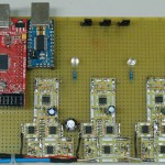
Open-BLDC SMD prototype and final prototypes

Open-BLDC SMD Prototype

Open-BLDC SMD Prototype

It has been again a long time since the last post. (I have the feeling to repeat myself here)

There have been some news on the Open-BLDC front. I have been on Motodrone two weeks ago. Because I took the plane to get there I realized that it will be too difficult to take the breadboard prototype with me. So on a short notice I soldered together a smaller version using smd parts. As an extra feature this prototype includes Allegro hall based current sensors. These will enable us to investigate vector control (aka. field-oriented control).

At first it worked perfectly. Sadly after some tests I burned two of the three bridge drivers. I only had one spare to replace, so I could not work on the software for long. Today I got replacement bridge drivers. Now I should have enough spare ones to compensate for more burning. 😉 So no news on the vector control front yet.

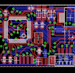
Open-BLDC Logic Board V0.1

Open-BLDC Logic Board V0.1

Open-BLDC Powerstage V0.1

Open-BLDC Powerstage V0.1

But I was not lazy while waiting for the replacement parts. I finalized the circuit and routed the logic board and powerstage. The powerstage was more or less straight forward but I am not very happy about the size and dimensions. I just am not sure if it is fittable on a standard Quadrocopter. Still it should be good enough as first etched prototype.

A much bigger challenge was the logic board. I somehow came up with this crazy idea to constrain the size of it to 45mm X 20mm. Still after many many hours of struggling with that puzzle I managed to squeeze all parts and wires into 45.5mm X 21mm! Yes you are right I am pretty proud of myself. I am still a routing beginner so the result seems to be good for me. 🙂

Now I have to wait so some other people review the work I did to try decreasing the amout of possible bugs in this boards. (If you like you can clone the repository here and check the stuff out, and give feedback on the mailinglist. (please subscribe before posting! :/ )) When I feel confident enough I will order some boards for testing and we can finally concentrate more on the software. 🙂