Tag Archives: electronics

New Black Magic Debug Maintainer

Hi everyone!

As some of you might know Black Magic Debug was created and maintained for many years by Gareth McMullin. He has created a wonderful tool that we all use and love. You might have also noticed that Gareth did not have much time to dedicate to the project for the last few years. He asked me a while ago if I would be able to take over the project and become an official maintainer of Black Magic Debug. I did not have the necessary resources to dedicate to the project until very recently. But it is finally time, from now on I am officially taking on the position as the Black Magic Debug maintainer. 🙂

I want to thank Gareth for putting the faith in me and creating this amazing project. I also have to say big thanks to Uwe Bonnes who stepped in while Gareth and I were unavailable to keep the patches and Black Magic releases going.

I have a lot of plans for the Black Magic project, software/firmware and hardware wise. You might have noticed I already spent some time catching up on and cleaning the GitHub issues. It is by no means finished and probably never will be, but I hope we can keep open issues and pull requests on a better level going forward.

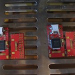
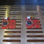
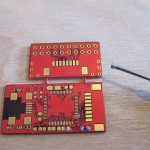
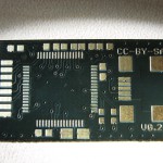
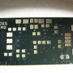
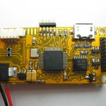
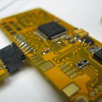
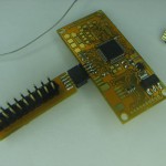
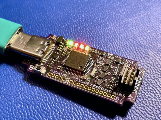
To resolve the issue that the native Black Magic Hardware is currently not available due to chip shortages, I am working on the new revision of the native hardware. This should make them available again and allow us for more alternative chip choices. We are adding some cool new features to the new hardware while we are at it. (more information soon) I am also working on a tool that will help users manage the Black Magic Probe firmware, opening doors to more flexibility and versatility of the project overall. (also, more information about that soon)

A small teaser of the new native Black Magic Probe hardware V2.3a
3D Printed cases for BMP V2.3a

You can also expect that we will finally get a proper CI system including HITL (Hardware In The Loop) testing. Something we are in dire need to keep the stability expectations as high as possible. I was collecting a lot of hardware over the years and I want to put it together to some good use. We will also improve the contribution process and document the APIs better, this should hopefully make addition of new targets easier.

There is one more thing that I would like to mention. In the process of changing maintainership the GitHub organization that the project is under will be changing it’s name. As it is not developed by Blacksphere (Gareth’s consulting company) we will be renaming the org to the project’s name itself. It will serve as an umbrella for additional repositories related to the Black Magic Debug project. Don’t worry GitHub should redirect the old organization names to the new one. I hope it will not cause too much disruption. We will also finally be officially retiring the SourceForge project page to avoid confusion. This means the old unused mailing lists will be disabled.

If you have questions or concerns and want to get in touch with the project you have multiple options: open an issue on github, join the 1BitSquared Discord server and talk to us in the #blackmagic channel. If it is something you would rather discuss one on one, you can also write an email to: contact at black-magic org where you will be able to reach the core developer team.

I am excited to work with you all to bring the Black Magic Debug project to the next level.

Stay safe, cheers,
Piotr Esden-Tempski

My Streaming Setup and Electronics Tools Collection

Hello everyone!

As many of you ask about the tools I am using for twitch streams as well as what electronics related tools I am using. I decided it was time to put together a blog post for that. I will likely keep updating this specific post when my streaming setup evolves or I need to add more content. This blog post is derived and updated version of the Gist that I posted a while ago.

This post is currently reflecting the gear I am using in May 2020. If you think anything is missing from this list or it is not up to date any more. Feel free to ping me and I will do my best to update the list! 🙂

Computer

Currently I use a scratch built PC for streaming, here is the list of the major components:

  • AMD RYZEN 7 3700X 8-Core
  • Gigabyte X570 Motherboard
  • 64GB of RAM
  • Gigabyte Radeon RX 5600 XT GPU
  • EVGA SuperNova 650 G3 modular power supply
  • Noctua NH-U14S 140mm SSO2-Bearing CPU cooler
  • Fractal Design Meshify C Black Compact Mid Tower case
  • Two 1080p Dell monitors I had since years

For the complete build and the exact parts used you can find the NewEgg build here: https://newegg.io/a1664311

Cameras

Lighting

Capture Devices

Audio

Software

  • Main Streaming software: OBS
  • Linux Browser view used for overlays and plugins
  • Free Plugins/overlays from Streamlabs
  • AlertBox: Displays alerts of new followers, subscribers, bit donations and more
  • ChatBox: Displays the twitch chat messages as video overlay
  • Cloudbot: Provides commands like `!uptime` and automatically sends out an invite to the Discord server.
  • Key and Mouse visualizer: TrayKeys
  • Text Editor: Sublime Text
  • ToDo List Sublime Text Plugin: PlainTasks
  • PCB Design Software: KiCad
  • FPGA Tools:
  • Logic Analyzer framework/software: Sigrok/Pulseview

Other Gear

1BitSquared and other stuff

If you like what you see and would like to support the streams and development of new open source devices, but you already have all the 1BitSquared hardware you need, you can support me through Patreon and/or Twitch subscriptions.

You can reach me through twitter and on our 1BitSquared Discord server. I hope this list is useful.

Cheers,
Piotr

Open-BLDC and the CLogic story

Castle ICE HV to Open-BLDC Mod Tutorial Step 10

Hi,

It was again a while since my last post, but as always I was quite busy. 🙂

The last news about Open-BLDC was about its V0.3 iteration. A lot has changed and happened since then. I was realizing that I am getting more and more inquires where people were asking about obldc being able to control very different sizes of motors, ranging from 12V and 10A up to 48V and 200A.

This requirement does not really ask for different logic and controls but it definitely asks for many different power stages. Open-BLDC was designed to be modular from the beginning but still to accomodate that kind of a power range it would be necessary to design and create quite a big lineup of hardware.

Around that time I had the opportunity to take a look inside a dead motor controller from Castle Creations just to realize that these guys seem to know what they are doing and that they went with a modular design too. To make a long story short I decided that it will be better to buy one of their of the shelf motor controllers and retrofit them with my logic. That is how CLogic was born.

As it seems other manufacturers are selling ESCs that have the same interface between the logic and the power stage too. Tekin for example. But my guess is that they are just OEM of castle themselves. But who knows. 🙂

Turingy also came out with an ESC that seems to have the same interface, the Turingy dlux. I ordered a few of them to take a look for myself and see if CLogic will fit in there. That would be a great source of cheep power stages. 🙂

CLogic has most of the functionality the Open-BLDC v0.3 had. Because of the size constrains I had to get rid of the dedicated i2c and PPM connectors, but I added isolation on the CAN interface that should provide additional safety when used on a 50V and bigger systems. The i2c and PPM interfaces are still available either over the new AUX connector or through the UART interface connector.

The new AUX connector gives the possibility of easily connecting encoders or hal sensors for sensored operation. So the interfaces stay very flexible with added flexibility due to the big variety of power stages you can use, while being very very compact.

Sure some people complained “The power stages are not Open-Source!!!”, yes that is true. Also these systems start at a higher power and weight class than some of you would want to operate them. That is why there is CPico Power. It is a very small, low power and a hopefully cheep power stage that we are putting together for those who want it all fully open! So no worries. 🙂

I think that wraps up the news about the new direction Open-BLDC is going. I hope you like it. I am looking forward to your comments.

Cheers Esden

FLOSS-JTAG V1.0 Released and Available

Hey everyone,

As you might know some time ago I have developed a small JTAG adapter based on the FT2232H chip. I gave it the name FLOSS-JTAG as the idea was that it should be absolutely OpenSource and OpenHardware.

You can find the project at GitHub and some more info at it’s random projects wiki page.

FLOSS-JTAG not only has the high speed 24MHz FT2232H chip (there are some designs based on my idea that are using a low speed version of the same chip). It provides the new standard 0.05″ pitch 10 pin Cortex JTAG header as well as a TTL level serial interface on it’s second interface.

I am glad to announce that I have reached the V1.0 with it. All necessary files to make your own are in the GitHub repository. But if you don’t want to go through the pains of ordering PCB, sourcing parts, assembling QFN SMD packages you can also purchase it in the Joby Robotics online shop.

At Joby Robotics you get a cable assembly to connect the FLOSS-JTAG to a target. This allows you to debug and connect to targets that are difficult to reach otherwise. You also will get a cortex connector to old standard 20pin 0.1″ pitch connector adapter.

The adapter is small and will make it also easier to debug targets that are difficult to reach.

You can get precrimped Molex Picoblade wires in 10 different colors at Joby Robotics too. This way you can easily build a UART cable that connects FLOSS-JTAG to a device.

I am very happy that FLOSS-JTAG is finally easily accessible to anyone who needs it.

FLOSS-JTAG works perfectly together with Openocd and Summon-ARM-Toolchain.

Cheers Esden

Open-BLDC V0.3 Hardware Based Closed Loop Control

Hi,

Good news everyone!

After again a way too long time some new news! I finally implemented hardware based commutation detection and the associated closed loop controller.

That was quite a run because of a cascade of timing and timer problems. And a very nasty compiler bug. But now it works and very well on top of that. Woohoo o/ But see for yourself in the video.

The video also shows the new implementation of the startup routine. It uses now a separate software timer. It was made possible by using SysTick as timer base and implementing the timer in software. This way it is easy to add new timers that don’t need to be very time precise, as it is the case in startup, or ignite as I like to call it. 🙂 The old implementation was using timer overflows of the commutation timer that led to nasty speed jumps while starting up and made the startup unreliable.

Next step, put Open-BLDC on a plane! 🙂

As always you are welcome to drop by in #open-bldc channel on freenode if you have questions or just want to hang around to follow the cutting edge development. 🙂

Open-BLDC v0.3

Open-BLDC V0.3 Full Front
Hey everyone!

Just a short update so that you don’t think that I have disappeared completely. 🙂

Lately I am really busy so that is why my updates here are very rare. I have moved to California few months ago to work full time on Open-BLDC and Paparazzi. Although Open-BLDC got quite a bunch of attention there is still a lot to do, and this project is still not in a state where it is possible to put the controller on a vehicle and fly with it. 🙁

There is some good and bad news. I got the sampling based commutation detection running pretty good. There is an issue with it. Because you can sample the BEMF only once a PWM cycle the resolution prevents turning the motor very fast without adding some kind of an estimator or at least a PLL. So currently only 4000RPM with a 7pole pare motor are possible. 🙁

That is why I started working on Open-BLDC v0.3 hardware. It is assembled now and you can look at some pictures here. It has a comparator integrated into the power driver board to make commutation detection really easy and have something usable _NOW_. I also found out that using many small mosfet’s is much more efficient then using single big ones. The gate capacitance is lower, the heat dissipation is easier, the on resistance is tiny. The only question is if they will distribute the power evenly between the switches. That is still something that has to be tested. But the power stage board looks really pretty with all those tiny fets on it. There are many more other smaller and bigger improvements that would be too much for such a small post.

I am currently bringing up one subsystem after another. I had to change some of the connections to the STM32 which means that I have to change the low level drivers and it is always a pain to do.

Anyways, there is progress and Open-BLDC is not dead! I am working on it. And I am sorry for not keeping you guys more up to date. As always I will try to be better about that. 😉

Floss-JTAG V0.1 Assembly and V0.2 boards.

Because I wanted to have a small JTAG adapter with additional UART port and a different (smaller) connector then what is available out there, I have decided to make a JTAG adapter. I chose the FT2232 USB adapter chip. This guy is pretty nice because it has a special engine inside that is supporting many different protocols. One of them is JTAG. I have released what I made as always on GitHub under the CC-BY-SA 3.0 license. There is no software needed on the adapter side so no software included. All you need is OpenOCD. It now even has a config file dedicated for Floss-JTAG. Calling for example:

#> openocd -f interface/flossjtag.cfg -f board/open-bldc.cfg

will connect to Open-BLDC using the Floss-JTAG adapter.

Building Floss-JTAG I learned a nice lesson. Always check your footprints 10x before you send the gerber files to the manufacturer!!! I had to customize the footprint for the FT2232 chip and made a mistake. The pads were not long enough so the pins had only 0.1mm overlap area. It was a real pain to solder that. I assembled 3 of Floss-JTAG using this design. Sadly only two are working.

Because of that mistake I immediately corrected the board layout and sent it out. I got the boards today. I hope that there is no other mistake hidden somewhere. 🙂 Attached are the images of V0.1 assembly and of the V0.2 boards.

Open-BLDC V0.1 Fully Assembled

I finished soldering Open-BLDC V0.1 boards and took some pictures while doing so.

After connecting it to the power everything seems to work properly and nothing is burning. That is really good news.

One little thing that is bothering me. The board draws 60mA, what is a value that I expected. The 5V linear regulator gets really warm. I am not sure if that will be a problem or not. But I did not find any other problems or screwups yet, even the big MOSFETs can be soldered using a simple soldering iron. It takes some time though, because the board and the MOSFETs are monstrous heatsinks.

More news coming up as soon as I start playing around with the software.

Open-BLDC V0.1 is alive!

I assembled the basic STM32 circuitry of Open-BLDC and it works. I also made a video showing the logic board and blinking around. I know it is a bit pointless but I love blinking LED’s! 😉 I wrote the software using libopenstm32.

Have fun:

Video on Youtube and here the same video on Vimeo.

While assembling Uwe and I made some photographs that I don’t want to hold off either.