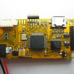
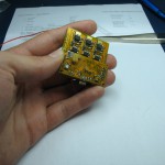
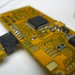
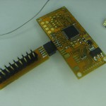
I am currently working on building a breadboard prototype of Open-BLDC. I will write about that in more detail in a separate post. I had a problem there. The Olimex STM32 board has two dual in line connectors that just don’t fit on a breadboard. There are some adapters that you can buy for money, for example from Number Six. But that would cost me too much time and money.
So I decided to build my own adapters with parts that I had ling around and a prototype board that I got from Uwe. (Thanks Uwe I will buy one and give you a replacement as soon as possible!) It was a lot of fun building the adapters. They are really easy to make!
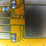
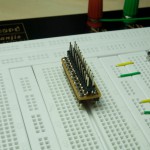
Step 1
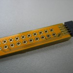
Just cut out piece of prototype board with the length you need and four holes wide.
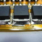
Step 2
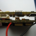
Solder a dual in line connector to the copper side of the board. Just don’t push the connector completely into the holes so that you can reach the copper with your soldering iron.
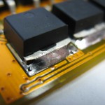
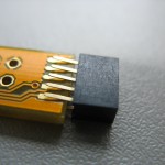
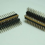
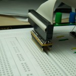
Step 3
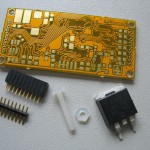
Solder two single line pin connectors on the other side of the board, right and left of the dual connector.
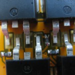
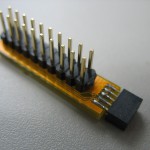
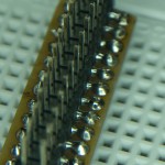
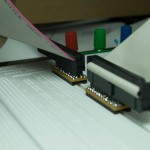
Step 4
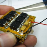
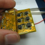
This is a bit tricky. You can use some wire to connect the pins of the DIL (Dual In Line) with the single line connectors. But I found out it is much easier just to put a bit more solder between the pins and let them connect. You may have to try one or two times. Having some desoldering wick around is a good thing if you happen to solder together wrong pins. ^^
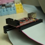
Step 5
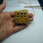
Profit! 😉
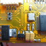
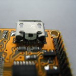
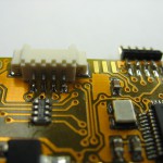
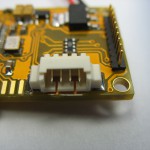
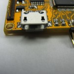
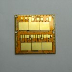
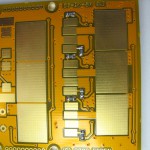
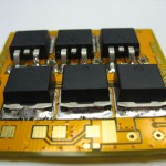
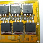
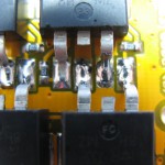
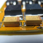
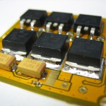
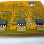
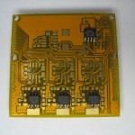
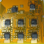
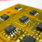
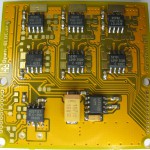
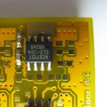
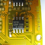
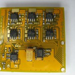
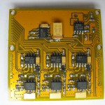
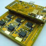
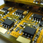
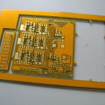
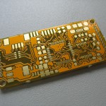
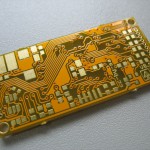
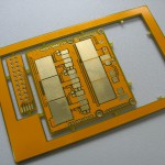
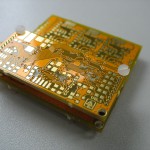
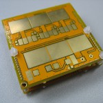
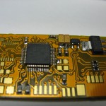
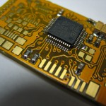
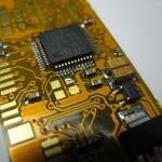
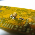
I appended some images you may consider more or less useful. I should make one more adapter to document the build process. :/ I am sure there will be such an opportunity soon.
Cheers Esden