Because I wanted to have a small JTAG adapter with additional UART port and a different (smaller) connector then what is available out there, I have decided to make a JTAG adapter. I chose the FT2232 USB adapter chip. This guy is pretty nice because it has a special engine inside that is supporting many different protocols. One of them is JTAG. I have released what I made as always on GitHub under the CC-BY-SA 3.0 license. There is no software needed on the adapter side so no software included. All you need is OpenOCD. It now even has a config file dedicated for Floss-JTAG. Calling for example:
#> openocd -f interface/flossjtag.cfg -f board/open-bldc.cfg
will connect to Open-BLDC using the Floss-JTAG adapter.
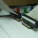
Building Floss-JTAG I learned a nice lesson. Always check your footprints 10x before you send the gerber files to the manufacturer!!! I had to customize the footprint for the FT2232 chip and made a mistake. The pads were not long enough so the pins had only 0.1mm overlap area. It was a real pain to solder that. I assembled 3 of Floss-JTAG using this design. Sadly only two are working.
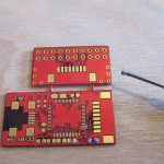
Because of that mistake I immediately corrected the board layout and sent it out. I got the boards today. I hope that there is no other mistake hidden somewhere. 🙂 Attached are the images of V0.1 assembly and of the V0.2 boards.
-
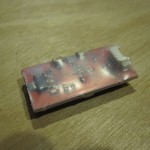
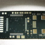
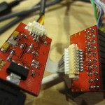
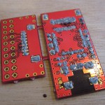
- Finished Floss-JTAG V0.1 Back
-
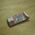
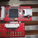
- Finished Floss-JTAG V0.1 Front
-
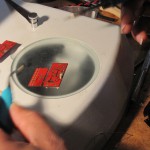
- Floss-JTAG V0.1 After Reflow
-
- Reflowing two more Floss-JTAG V0.1
-
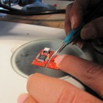
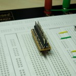
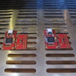
- Aligning parts on Floss-JTAG Before Reflow
-
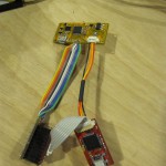
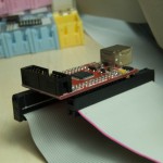
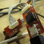
- Floss-JTAg V0.1 connected to Open-BLDC Logic Board
-
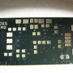
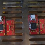
- Assembled Floss-JTAG V0.1 Back
-
- Assembled Floss-JTAG V0.1 Front
-
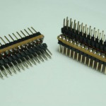
- Parts before reflow
-
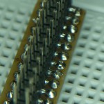
- Dispensed solder paste
-
- Solder paste dispension