
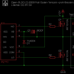
Circuit
For testing you can take a big capacitor, so that when you manually switch on the high side you see something happen. I took a 330uF capacitor and it is enough to turn the high side MOSFET on for about 30 seconds. Still you have to be careful because the capacitor only gets charged when the low side MOSFET is turned on. So after turning on the power the capacitor is not charged and you have to turn the low side MOSFET on first, then turn it off again and finally switch the high side on.
In the final design one should probably select the right bootstrap capacitor. The equation for calculating that value is described on page 6 of the International Rectifier application note AN-978.
You can probably get rid of the capacitor and the diode if you connect VCC directly to VB. The problem you get then is that when the current on VS gets higher then 12V you get a problem. But I may be mistaken. Correct me if I am wrong.
Conclusion: read the damn application notes and I still have problems with understanding the electrical engineer talk! 🙂
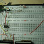
I hope this helps someone. You can see my circuit for one half bridge attached to this post. And a picture of my breadboard.
I use the two LEDs to see what happens with the MOSFETs. They are glowing a little when both sides are off. The one connected to 12V is switching off when the high side is on and the one connected to GND switches off when the low side is on. I love LEDs! 🙂
Cheers Esden
-
- Circuit
-
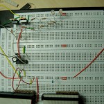
- Powerstage Off
-
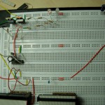
- Low Side On
-
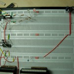
- High Side On Capacitor Charged
-
- High Side On Empty Capacitor
hai,
I am doing my project in sensorless control of BLDC. Right now I am implementing a 3-phase inverter for driving the motor. I am using 3, IR2110 for that. But the circuit is not giving proper output. I am getting both low side and high side pulses from the Ic, but when connected to the Mosfet bridge I am not getting any output. I am using 0.47microFared capacitor for Bootstrap operation.
Please do give me a helping hand, so that i can fix the problem.
Thanks in advance,
Waiting for your replay,
Saji Justus
I am not sure what your problem is. But you have to remember that the bootstrap capacitor only gets charged when you open the low side of the half bridge. The low side should always work independent from the charge of the bootstrap capacitor.
I hope this helps.
Hi, dear Saji Justus. I am Amin. I am implementing a 3-phase inverter for driving the motor. I am using 3, IR2110 for that like what you did before. I have a problem on the high side pulses when I use mosfet driver . the low side works well but the problem is just on the high side. I’am working on this problem more than two months and lost many mosfets. i’am getting bored and i don’t know how to solve it. If you could help me I really appreciate you. Would you please send me the shematic with correct amount if you have.
thanks in advance.
please reply. I’am waiting for your help
How about a progress update, its been about a month since this post. I’m very interested in this project as I’m working on a personal project w/ STM32, CAN, and looking into my own BLDC controller for RC motors. (Tri-Rotor instead of Quad-Rotor). Anyways, I’d like to see if I could contribute in some capacity to this project, i’m experienced w/ embedded systems, mechatronics, and RTOS. Have you gotten a prop spinning yet?
Yes I really should write a progress report. There is a lot happening “behind the scenes” well not so much behind the scenes. You can subscribe to the commit mailinglist here: https://open-bldc.org/cgi-bin/mailman/listinfo/open-bldc-commits I am trying to check in everything I do there. Last week I was able to drive a motor using the stm32 and my breadboard prototype. I am currently taking a look at different PWM schemes and ways of detecting commutations. It is not so easy if you want to do it the best way possible! 🙂
But well as I said I really should write an update soon. 🙂
P.S. You can nearly always reach me in the #uavp channel on the freenode irc network, if you want to get involved or just get a status report. (http://freenode.net/) 🙂
hi, utsav here.can ne 1 tell me what capacitors n diodes i should use.
I want to drive igbt rated 1200 v and 60 A. plz help i have deadlines to complete the project…
You can find the pointer to that information in the datasheet. You can find the formula for calculating the bootstrap capacitor value in design tip DT98-2 section 3. It depends on the “Gate charge of high side FET”, “frequency of operation”, “Bootstrap capacitor leakage current” and “level shift charge required per cycle” (the last value is in your case 20nC for 1200V). So I can not provide the exact capacitor value for you, you have to calculate it yourself.
i guess i have d answer to sajis problem, though not quite sure
the i/p capacitance of ur mosfet is too high. ir2110 may noty be able to drive such a high capacitance.. try ur luck with 3120 chip.. its better than ir2110 for driving mosfets.