Hey everyone!
Today I had to fix another STM32F4 Discovery board. By fixing I mean replacing the STLink firmware with Black Magic Probe firmware. I do that on a semi regular basis but as I have not done it in a long time I did not remember the process anymore. Obviously this calls for a blog post with some step by step instructions on how to do it, so that I have a reference in the future. Also you might find it useful yourself.
First of all let’s explain what we are trying to do. The objective is to replace the STLink SWD (Serial Wire Debug) firmware with Black Magic Probe firmware. The board is setup by default to use a smaller chip to run the STLink firmware to talk to the main stm32. We need to change the smaller chips firmware. The initial adjustments to the board are needed to be able to access the programming pins of the smaller chip and replace it’s contents to Black Magic Probe firmware so that we can use GDB (GNU DeBugger) to program and debug the board instead of the very unstable and unreliable proprietary STLink protocol. The adjustments needed to access the small chips programming pins need to be reversed once the firmware is changed to Black Magic Probe firmware, resulting with an stm32 f4 discovery board with Black Magic Probe firmware ready to use.
For the “Fixing” process I use a genuine Black magic probe, I have one of those very early ones with a 0.1″ header that is very useful in this particular case. You can also use a Black Magic Probe Mini with a PCB adapter, make an adapter cable or you can use another Discovery board that has already been “fixed”.
Step 1
First step is to change the two solder jumpers on the bottom of the discovery board.
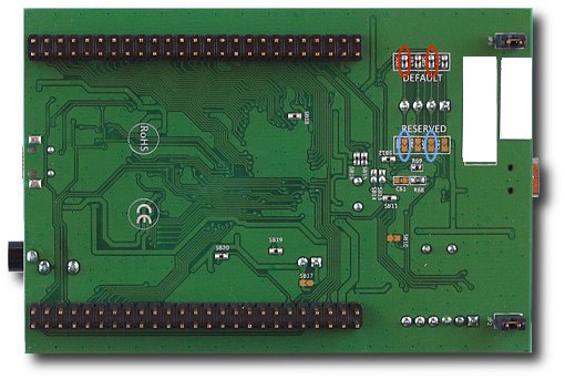
Jumper modification for SWD programming.
Remove the 0Ohm resistor/jumpers marked with red circles, and close the jumpers marked with blue circles.
Note: The easiest way to do that is to use a soldering tip, add a bunch more solder over the resistor and swipe them of. After that is done use solder wick to make sure there is no short on the “red” jumper. You can discard the 0Ohm resistors. It is much easier to just add a small blob of solder to close the “blue” jumpers, it is easy to remove them later in the process by just using some solder wick.
Step 2
Remove the SWD and slave MCU jumpers as indicated by the red circles in the photo.
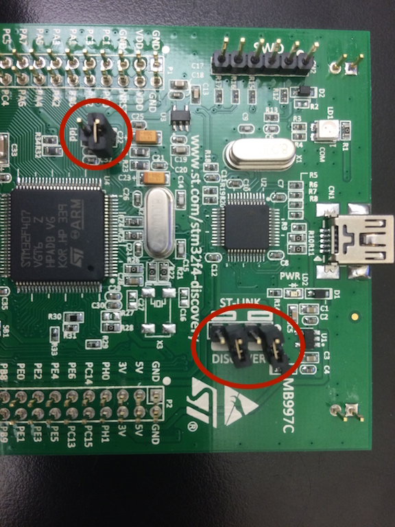
STM32F4 Discovery board Jumpers for updating the programmer chip firmware
Step 3
Attach jumper wires to the Black Magic Probe header.
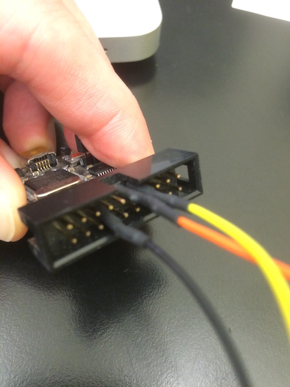
Black Magic Probe Serial Wire Debug connections for Discovery board “fixing”
Standard JTAG/SWD 20Pin 0.1″ header
- Black wire – Pin 14 (GND)
- Orange wire – Pin 9 (TCLK/SWCLK)
- Yellow wire – Pin 8 (TMS/SWDIO)
In case you are trying to figure out which pins these are on a standard ARM Cortex 10Pin 0.05″ header. Here you go:
Standard JTAG/SWD Cortex 10Pin 0.1″ header
- Black wire – Pin 3, 5 or 9 (GND)
- Orange wire – Pin 4 (TCLK/SWCLK)
- Yellow wire – Pin 2 (TMS/SWDIO)
Step 4
Attach the Black Magic Probe to the discovery board.
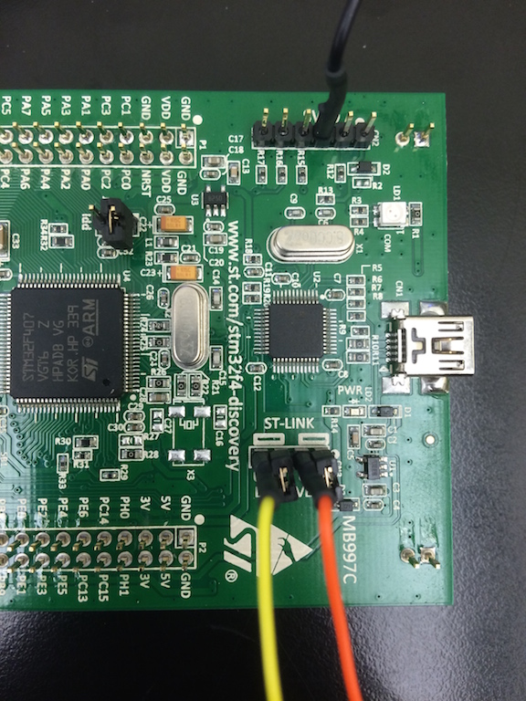
STM32F4 Discovery board Serial Wire Debug connection for “fixing” the on board programmer firmware
- Black wire (GND) – Pin 3 of the SWD (CN2) header
- Orange wire (SWCLK) – Pin 2 of the ST-LINK/DISCOVERY (CN3) header
- Yellow wire (SWDIO) – Pin 4 of the ST-LINK/DISCOVERY (CN3) header
Step 5
Now you can connect the discovery board and the Black Magic probe to your computer via USB. The order should not matter, but usually I tend to connect the usb wires to the laptop before connecting the SWD wires between the two devices, just to make sure we don’t have some strange current loop that powers one or the other via IO pins, which might be problematic.
Step 6
Now we turn our attention to the software. You can obviously do these steps before you wire everything up but this is the order I followed.
The process requires a few dependencies that you should install using either apt on Linux or homebrew or macports on OS X:
- Python
- pyserial
In my case I use OS X and homebrew so I needed to run the following two commands:
brew install python pip install pyserial
Step 7
Download and make the an arm gcc compiler “findable”. I recommend using GCC ARM Embedded as it is maintained by the ARM developers themselves and they seem to generally know what they are doing. 🙂
So download it from here: https://launchpad.net/gcc-arm-embedded
Then unpack it into your home directory:
[code language=”text” gutter=”false”] cd ~ tar xfvj ~/Downloads/gcc-arm-none-eabi-replace this with the version-mac.tar.bz2 [/code]
Then you should add the binary directory of the newly unpacked compiler package to your system. Obviously to do this you add the directory to your PATH environment variable. If you don’t know what that is you should learn a bit more about your Unix/Linux basics. 🙂
export PATH=~/gcc-arm-none-eabi-someversion/bin:$PATH
To make this addition persistent you can also add that to your .profile, .bash_profile or .zprofile depending on the shell and setup you use.
Step 8
Download blackmagic firmware source code. You can get it at https://github.com/blacksphere/blackmagic
The easiest way is to clone the github repository, look for the small window at the center right of the github page for the git repository url. If you have a github account choose the ssh url but if you refuse to do so then you can go with the https one too. 🙂
If you did not learn about GIT and GitHub yet this is the perfect time to take a break from all of this here and come back after you have caught up on your homework. 😀
git clone git@github.com:blacksphere/blackmagic.git
Step 9
Now let’s build the firmware. This consists of three steps:
- Fetch the libopencm3 submodule
- Build from the toplevel so libopencm3 is built
- Build the blackmagic firmware for the stlink
cd blacksphere
git submodule init
git submodule update
make
cd src
make clean
make PROBE_HOST=stlink
Step 10
We can finally connect to the hardware we wired up before and erase the pesky stlink firmware. When the discovery boards ship, the firmware is read and write protected on the STLink chip. So to be able to overwrite the firmware we will have to unlock the chip. Thanks to Gareth there is a small python script that can do that for us. You just have to call the following command inside the src directory of the blackmagic repository and it should be able to remove the write protection:
../scripts/hexprog.py -s -d /dev/cu.usbmodemSOMESERIAL1 -r blackmagic.bin
In the case you are on Linux you can leave out the -d device parameter. For reference the -s parameter tells hexprog to use Serial Wire Debug instead of JTAG and -r tells it to unlock and erase the target chip.
If you skip any of those two parameters it will not work for you.
Step 11
Flash the bootloader. We are getting very close. To upload the blackmagic bootloader you use arm-none-eabi-gdb.
arm-none-eabi-gdb blackmagic_dfu
target extended_remote /dev/usbmodemSOMESERIAL1
monitor swdp_scan
attach 1
load
exit
This sequence of commands attaches to the virtual gdb server that is provided by the Black Magic Probe on it’s virtual serial port 1. (The second serial port is the USB to serial interface located on the back of the BMPM) We then tell the monitor (this is the BMP) to scan using Serial Wire Debug as our protocol. Next we attach to the virtual process number 1. (As we are on the embedded systems there usually should only ever be 1 process unless you run an RTOS) We load the firmware from the elf file that we passed on to gdb earlier and exit GDB.
Simple right? 😀 (Believe me that is definitely simpler than setting up and making OpenOCD work with Eclipse)
Tip: To make things easier for the future you can add the following to your .gdbinit file:
set target-async on
set confirm off
set history save
set mem inaccessible-by-default off
tar ext /dev/cu.usbmodemSOMESERIAL1
mon version
mon swdp_scan
#mon jtag_scan att 1
Note: On Linux the cu.usbmodem device name will be /dev/ttyACM0 instead.
After setting up the .gdbinit file the upload process becomes quite a bit shorter:
arm-none-eabi-gdb blackmagic
load
exit
Step 12
Upload the black magic firmware itself. Here you have two options. Either you can use the same process as before using GDB or you can use the now uploaded DFU bootloader to upload the Black Magic Probe firmware payload. Using GDB you would run the following:
arm-none-eabi-gdb blackmagic
target extended_remote /dev/cu.usbmodemSOMESERIAL1
monitor swdp_scan
attach 1
load
exit
Alternatively you can upload the firmware using a DFU script. Before you do that though you should disconnect the genuine Black Magic Probe from your computer as you want to make sure the script flashes the Discovery board and not your BMP. To do that you will need to install python libusb as an additional dependency. But having done that you can then run the following to upload the firmware:
./scripts/stm32_mem.py blackmagic.bin
Step 13
Put everything back together. Now you just have to do four things:
- Disconnect your Black Magic Probe and Discovery board from your computer as well as each other.
- Remove the solder blobs you have added on the back of the board.
- Add solder blobs to where you removed the resistors at the very beginning.
- Put the jumpers back to where they were on the front of the Discovery board.
You are pretty much done now. If everything went well you should have your “fixed” discovery board. Follow to the one additional step below to test that.
Step 14
Plug in your Discovery board into your computer. The dual color led next to the USB connector should be solid Green. If it is blinking Green it means the bootloader is running and the board is expecting to be flashed with the firmware. This can happen if you still have the power jumper disconnected that provides power to the “slave” STM32F4 chip. This is actually very useful if you want to upgrade the Black Magic Probe firmware on your discovery board. 😀
Additionally if everything went well if you are on Mac OS X a /dev/cu.usbmodemSOMESERIAL1 and /dev/cu.usbmodemSOMESERIAL3 should appear. If you are on linux you should be able to find ttyACM0 and ttyACM1 in the /dev directory.
I hope this write up is useful for you and the future me. 🙂 I am planning to write another blog post on how to build and upload an example firmware onto the slave processor. So hold on to your hats! 🙂
Cheers,
Esden
P.S. Big thanks to Jack Ziesing for proofreading and introductory paragraph and sparking the work on this article. It is a great help! 🙂
Is it any simple way to run GDB connected to BMP right from Eclipse debug config?
Thanks to your post, I create file .gdbinit, and successfully run from cmd.exe,
but it would be pleasant to configure Eclipse to run GDB with .gdbinit.
There are a lot info about OpenOCD + stlink_v2 – so now it is easier to configure OpenOCD,
then BlackMagic Probe.
Pingback: Introdução à Black Magic Probe | Blog do Sergio Prado